CASE STUDY
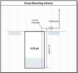
For a petrochemical plant, customer ordered an Air Operated Double Diaphragm pump to lift water from an underground pit for intermittent application. The pit was 5 meter deep and customer had to mount the pump on the ground level. The flow required was 5 m3/hr and they were draining the water to close by pipeline with 10 meter head. 1” Aluminum pump with Buna diaphragm was selected.
During detail engineering, one of the pump expert remarked, “Pump may be able to lift the material but will not deliver the required flow.” What did everyone else seems to miss that the expert got?
ACCELERATION HEAD LOSS
Positive displacement pumps- few rotary and all reciprocating type- create pulsating flow. These flow pulses occur because the pump’s liquid chamber/s are repeatedly filled with liquid on the suction stroke and then pushed out on the discharge stroke. This pulsating flow results in damaging vibration, pressure surges, and increased noise.
Flow from a piston or diaphragm pump is not linear- it accelerates at the start of the pump stroke, reaches maximum velocity at the mid point, and decelerates to zero flow at the end of the stroke. While the flow is accelerating and decelerating, the fluid pressure at the pump’s discharge is increasing and decreasing. Peak flow from the pump can be as much as three time the average or mean flow, creating an acceleration head phenomenon.
The design and construction of a liquid pumping system is often concentrated on ensuring that the desired pressure and flow are achieved at the downstream of the pump. Frequently, pump inlet conditions are not given proper consideration in the system design. Given the acceleration head loss phenomenon, it is even more critical to include complete design analysis of pump inlet conditions for reciprocating pumps.
NPSHA and NPSHR
Net positive suction head available (NPSHA) is the pressure in the feet of liquid absolute measure at the pump suction port, less the vapor pressure. Hydraulic Institute specifies a measurement of procedure for NPSHR, which is at the point that a reciprocating pump loses 3.0% in volumetric efficiency relative to a stable efficiency at a high suction head. NPSHR must be supplied by the pump manufacturer. If the NPSHA is less than NPSHR, the pressure at some point in the suction area will be less than the vapor pressure of the liquid, cavitation will take place in the pump.
NPSHA is often expressed as net positive inlet pressure available (NPIPA) and net positive inlet pressure required (NPIPR). There terms reflect the use of pressure units (psi or bar) rather than feet.
Acceleration head loss is frequently forgotten in calculating NPSHA. The liquid mass in the suction line to the pump must be started and stopped with every pump stroke. The pump must expend energy to accelerate the liquid into the pump during the suction stroke and then stop the inlet flow on the discharge stroke. This is acceleration head component of NPSHA for reciprocating pumps and can be calculated using below formula:
ha=LVnC/Kg
Where
ha = Acceleration head loss in feet
L = Actual suction pipe length in feet
V = Mean flow velocity in suction line in feet/sec
n = Pump speed in cycles per minute
C = Constant (Depends on pump type)
K = A factor representing the reciprocal of the fraction of the theoretical acceleration head which must be provided to avoid a noticeable disturbance in the suction line
g = Gravitational constant (32.174 ft/sec2)
V= 0.0485 * Q/D2
Where:
V = Mean flow velocity in suction line in feet/sec
Q = Flow rate in gallons per minute
D = Pipeline inside diameter
|
Constant |
Pump Type |
|
0.200 |
Duplex single-acting (diaphragm pump) |
|
0.115 |
Duplex double acting |
|
0.066 |
Triplex (single or double acting) |
|
0.040 |
Quintuplex (single or double acting) |
|
0.028 |
Septuplex (single or double acting) |
|
0.022 |
Nonuplex (single or double acting) |
|
K |
Liquid |
|
2.5 |
Hot Oil |
|
2.0 |
Most Hydrocarbons |
|
1.5 |
Amine, glycol, water |
|
1.4 |
De-aerated water |
|
1.0 |
Urea and liquids with small amount of entrained gases |
BACK TO CASE STUDY
The expert showed the following calculations:
NPSHA without acceleration head loss : 4.6 MWC (Meter of Water Column)
NPSHR : 2.5 MWC
NPSHA is more than NPSHR- so it should be acceptable. However, let’s calculate acceleration head loss- it’s more than 8 MWC- of course the pump will not deliver the required flow.
We changed the suction pipe from 1.5” to 2” size and pump from 1” to 1.5”. The resultant acceleration head loss changed to 1.5 MWC.
NPSHA with acceleration head loss : 3.1 MWC
NPSHR : 1.7 MWC
Of course, the 1.5” pump with larger suction pipeline size (2”) will not only prime with 5 meter lift but also deliver 5 m3/hr flow rate.
OVERCOMING ACCLERATION HEAD LOSS PROBLEMS
- Reduce Acceleration Head Loss
- Increase pipe line diameter to reduce friction loss and liquid velocity
- Move the pump as close as possible to the source of the supply to reduce the mass that must be reaccelerated on every stroke and to reduce friction loss
- Straight pipe for at least 10-15 pipe diameters at the pump inlet to minimize turbulence
- Use larger pump to allow for slower stroke speed
- Use multiple chambers to reduce acceleration head loss
- Volume Bottle (Stand pipe):
Standpipes provide an area of accumulation and release of pumped liquid as the pump’s inlet valve alternatively opens and closes. Typically, the stand pipe needs to be 1.5 times the diameter of the suction pipe line, as tall as the supply tank height, and mounted within 25 (preferably 10) pipe diameters from the pump’s suction. The standpipe must also be capped and typically vented to the supply tank. Therefore, it can’t be used on suction lift applications. The other problem with standpipes is that they can become waterlogged and rendered ineffective when trapped air at the top becomes entrained in the liquid accumulated in the standpipe.
- Inlet Stabilizers
Essentially a pulsation dampener, an inlet stabilizer has a flexible internal diaphragm or bladder to prevent mixing of the system liquid with the stabilizer’s gas charge. Properly sized and installed in a tee 10 pipe diameter of the pump inlet, it can usually reduce acceleration head loss to less than 3 to 4 psi. It does this by accumulating liquid during the pump’s discharge stroke and releasing the liquid back into the suction line during the pump’s inlet stroke. In effect, the inlet stabilizer uses the stored energy of the compressed gas to reaccelerate the liquid back into the suction line. It will only have an effect on the liquid between it and the pump inlet so proper location is critical. Special inlet stabilizers are available for suction lift applications
CONCLUSION
In conclusion, it is important to consider several factors related to inlet piping for positive displacement pumps, specifically reciprocating pumps and peristaltic (or hose) pumps. Acceleration head loss is very important element when calculating NPSHA. Since acceleration head loss depends on both system parameters (pipe diameter, length, liquid details etc) and pump sizing (stroke rate, pump type- single acting or double acting, no of heads), acceleration head loss calculations are often overlooked and misunderstood. With suitable system design at the pump inlet, which may include standpipe or inlet stabilizer, improved pump performance will be obtained by reducing acceleration head loss.